2AZ-FE Ignition Coil electrical harness clips


#12
 02-15-2015, 02:55 PM
This job is a massive PITA, and a good chance to really screw yourself over. That fourth wire (ground, which is WHT/BLK) snapped at the little square connector that magically locks into the clip. There was no repairing that, so I bought a new clip which had the four wires already in it to splice in.
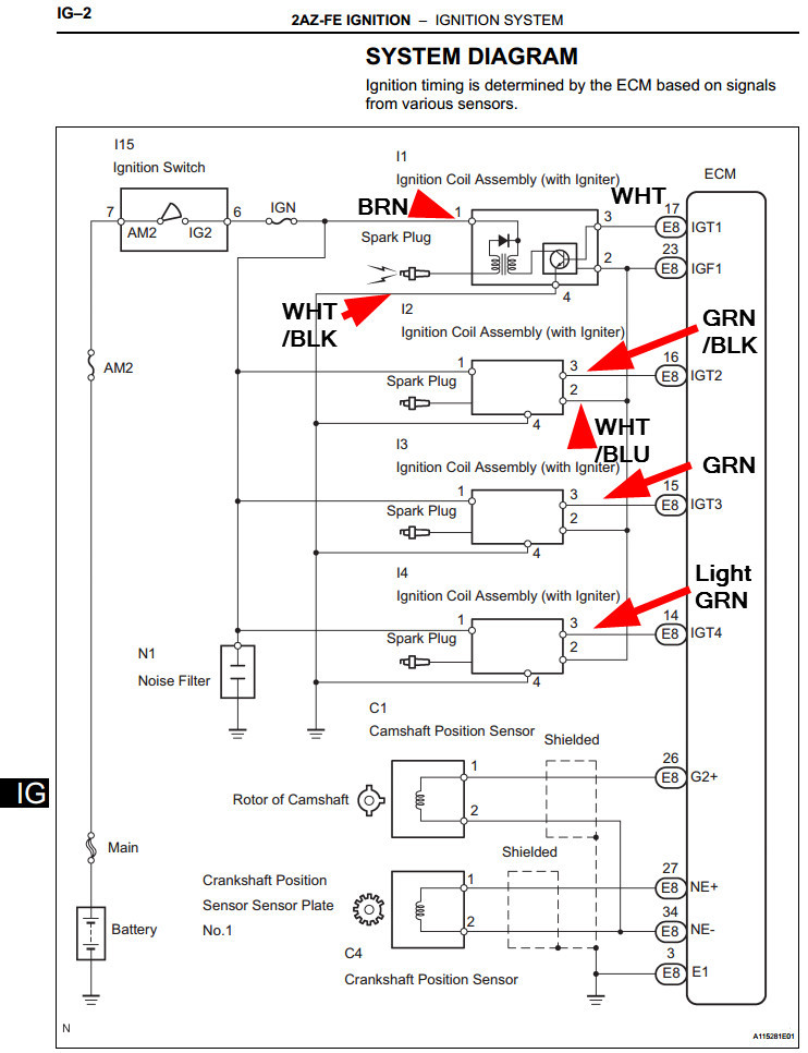
Sort of a good thing, as I had somehow put the wires in wrong I think, on the replacement clip I was using initially (when the ground wire snapped). From what I can tell from wiring diagrams in the FSM (they do not color code the wires, at least not the pages I found on Google search), the brown wire is the power wire, from the battery. They goes to pin 1 for all coil packs. Pin 4 is the ground wire, which is WHT/BLK. This seems to be the case for all four coil harnesses. According to the diagram, the positives and grounds all join together somewhere to run to their respective locations.
Each coil has a WHT/BLU wire as well, that appears to be Pin 2. All of those also join together and connect to the ECM at E8 (location 23). Pin 3 is different per coil. Hard to tell initially (especially in low light), but coil 4 has a pale green wire, 3 has a dark green wire, and 2 has a GRN/BLK wire. Each of these go off to the ECM E8, but to different spots (IGT2, IGT3, IGT4). For coil 1 that wire is solid white, going to IGT1.
Anyway, I had swapped the brown and wht/blu, but had not ignited the engine since ground was broken. When I was fixing it all today (after the part was delivered to the wrong house a week ago, and the person brought it by yesterday). I think if I had left it that way I may have shot crank amps into the ECM. Could have been bad.
Anyway, I did a hack job of soldering in the new connector, and now it fires up fine. Moral of the story is, the connectors are a beyatch to get off (the wires somehow lock into them), and if one of them does not slide in well, you run a big risk of snapping the connector off the wire, as it is a weak point.
Avoid doing this if possible. Make sure to write down the wire codes before, and if you do go for it, better have a backup plan if a wire snaps. The middle wires (pins 2 and 3) are something like 18 gauge, so they are really thin. The positive and ground wires are heftier (I think 14 gauge). Anyway, a suck job.
#13
02-15-2015, 03:07 PM
Wire diagram with color coding. Would have made my life easier if I had this to begin with! I added the colors. All Pin 1 wires are BRN. All pin 4 wires are WHT/BLK. All pin 2 wires are WHT/BLU. Then each Pin 3 has a unique color (coil 1 = solid white, coil 2 = GRN/BLK, coil 3 = GRN, coil 4 = pale GRN).

Thread
Thread Starter
Forum
Replies
Last Post
DIYDad
Engine & Internal
9
12-08-2014 08:55 PM