Toyota Camry 2007-2011: How to Replace VVT Sensor
What can go wrong with your Camry's Variable Valve Timing with intelligence system, and what can you do to fix it? The following article explains.
This article applies to the Toyota Camry (2007-2011).
Back in the late 60s and early 70s, the era of so called muscle cars, a number of street racers had their cam shaft’s reground to advance the moment at which the air/fuel mixture was sprayed through the input valve into the cylinder. This was done because at high RPM (i.e., illegal street racing speeds), the intake valve was moving up and down so quickly not all of the air/fuel mixture being sprayed into it had time to actually make it into the cylinder. By advancing the cam timing, more air/fuel had a chance to make it in at high speed (RPM).
The downside? At idle, cars with re-ground or modified aftermarket cam shafts ran rough, and could barely keep from stalling out. They only ran optimally at high speeds. But fuel efficiency was not a large concern back then — with gasoline costing well under $1 per gallon. And neither was exhaust pollution (except in places like Los Angeles), as the air/fuel that didn’t make it into the cylinder ended up being exhausted unburned, increasing the release of not only the methyl ethyl lead (these cars only burned premium fuel), but also nitrous oxides, etc., into the atmosphere.
But “green” advancements, such as the use of a fuel-rail system to recycle unburned fuel and “cleaner-burning” octanes of gasoline, changed this picture. Engine designers knew that an ideal way to get better engine operation at higher speeds would be to vary the timing of the camshaft — advance it for high RPMs, retard it for low. And over the years, such systems were introduced (the 1980 Alfa Romeo Spider offered a mechanical VVT system). But many of these variable valve timing systems were functionally unreliable, if not down-right troublesome.
Materials Needed
- Socket wrench set
- Set of metric sockets
Later engine improvements, coupled with the ever-improving use of computer technology and on-board controllers from first engine control modules (ECMs) to today’s powertrain control modules (PCMs), changed this landscape. Many variable valve timing systems were introduced by various auto manufacturers using widely different methods to accomplish the same end, including:
- Cam switching
- Cam phasing
- Oscillating cam, an
- Eccentric cam drive, and numerous others.
Toyota introduced a Variable Valve Timing (VVT) system in 1991, and its current “VVT-i” (Variable Valve Timing with intelligence) configuration in 1996.
This system uses a two-stage cam phasing system controlled by engine oil pressure to slightly modify the relationship between the camshaft’s drive chain and the intake camshaft that this chain rotates for optimum engine performance at different RPMs. Starting in 2005, the 3.5L V6 engine (2GR-FE) incorporated dual VVT-i system timing (one for each cylinder bank). The 2.5L I4 2AR-FE engine (replacing the 2.4L 2AZ-FE) introduced in the Camry in 2010 also came with VVT-i.

Toyota has also used an electrically-operated actuator to adjust intake camshaft timing in other vehicles (VVT-iE), but the Camry’s VVT-i system uses oil pressure to modify air/fuel intake timing — putting an additional burden on the engine’s already hard working, gerotor-type oil pump. It also reinforces the notion that the use of high-grade oil and regular oil changes is critically important to the long-term health of your engine, and not just from the viewpoint of effective metal-on-metal lubrication.
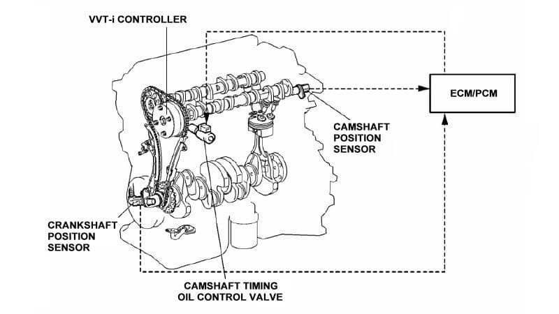
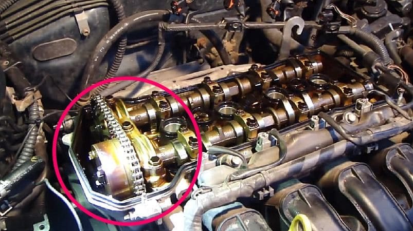
With VVT-i a solenoid, part of the “camshaft timing oil control valve assembly,” moves in and out to send and maintain a measured amount of pressurized engine oil to a wheel-shaped, "cam gear" actuator connected between the camshaft’s drive chain and the front of the camshaft.
When this actuator rotates clockwise (looking at it from the front), the camshaft’s position and timing of the air/fuel injection is advanced for high RPMs. Note that the timing of the exhaust valve closing and internal combustion remain fixed in this variable valve-timing system (other valve timing systems also modify valve lift and duration, such as Toyota’s VVTL-i system) produces the desired engine performance result.
But more engine complexity means more engine parts, and more parts means more things can go wrong. And problems with the Camry’s valve timing can result in the engine light coming on, a lack of power, or engine stalling issues.
There are a number of OBD-II fault codes related to valve timing and the camshaft position sensor in the Camry, including:
- P0340 — Camshaft Position Sensor Circuit Malfunction
- P0342 — Camshaft Position Sensor 'A' Circuit Low Input Bank 1
- P0343 — Camshaft Position Sensor 'A' Circuit High Input Bank 1
- P0345 — Camshaft Position Sensor 'A' Circuit Bank 2
- P0347 — Camshaft Position Sensor 'A' Circuit Low Input Bank 2
- P0348 — Camshaft Position Sensor 'A' Circuit High Input Bank 2.
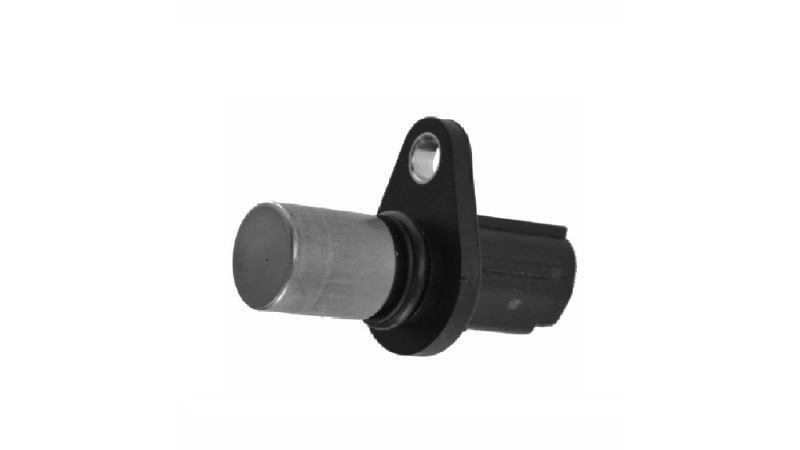
The variable valve timing sensor is often referred to as a camshaft position sensor (shortened to CMP). The camshaft position sensor is installed onto the cylinder head at the rear of the camshaft. It allows the PCM to “see” the position of the camshaft in relation to the crankshaft, and thus control ignition timing, fuel injection timing, and the VVT-i system.
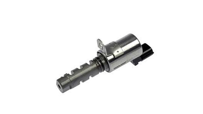
If the VVT-i system is acting up, a likely culprit can be the solenoid controlling the oil control valve assembly. The oil control valve (OCV) operation can be tested by checking the resistance across its two terminals (which should be 6.9 to 7.9 ohms), or by removing the OCV and running voltage across the two terminals to see if the solenoid moves the oil release plunger out. (Removing the voltage should send the plunger back in.) Replacing the camshaft timing oil control valve assembly is also a simple matter; a single bolt holds its flange in place, and an o-ring seals it.
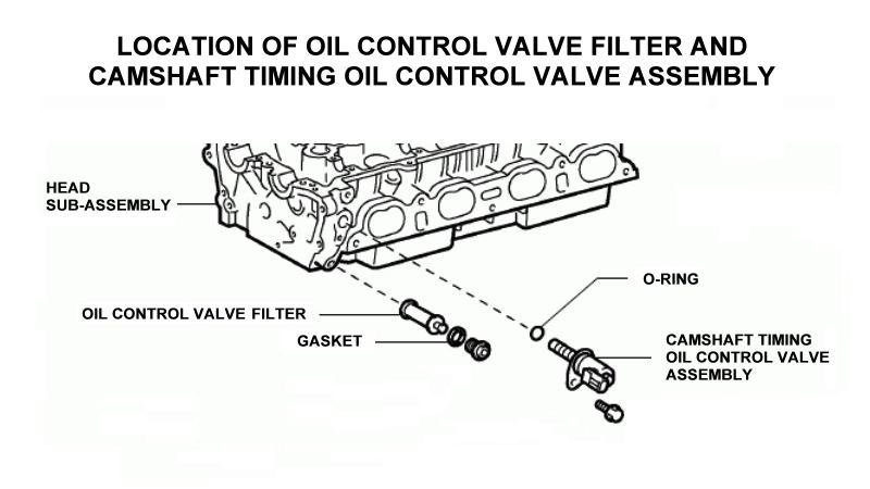
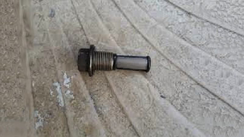
Note, too, that the OCV also has a filter screen, also called a “strainer,” in a nearby location that can become clogged with oil sludge. This screen can be difficult to get to, but extracting it is not complicated (removing a hex-shaped cap and gasket), allowing the screen to be cleaned or replaced with a new one.
If the oil control valve is functioning and the screen/strainer clean, the other likely culprit could be the camshaft position sensor (CMP). A camshaft position sensor is installed onto the cylinder head at the rear of the camshaft (each cylinder head for a V6). It allows the PCM to “see” the position of the camshaft in relation to the crankshaft, and thus control ignition timing and fuel injection timing for the VVT-i system.
Replacing one or both camshaft position sensors is straightforward:
Step 1 – Locate the camshaft position sensor
Nestled under the valve cover at the rear of the camshaft (and rear of the engine) is an innocuous-looking sensor usually held in place by one bolt. It has an electrical plug connected to it with wires that go to the PCM.
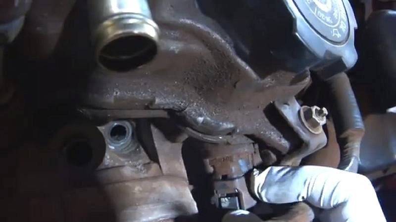
Step 2 – Replace the camshaft position sensor
Unplug the camshaft position sensor, unscrew the retaining bolt, and remove the sensor. Then replace the sensor with a new one and replace the electrical plug.
Related Discussions
- What Did I Break - CamryForums.com
- VVT-i Line - CamryForums.com
- VVT-i Actuator Malfunction - CamryForums.com
- Ruptured Oil Line - CamryForums.com