Toyota Camry 2002-2006: How to Replace Steering Rack and Pinion
The steering rack must be properly lubricated and correctly aligned for correct operation. If seals are leaking or a component is found bent, a rebuild or replacement is needed. Replacement involves a lengthy procedure; although, with a friend's help and the proper tools, it is very much doable.
This article applies to the 5th generation Toyota Camry (2002-2006).
The steering rack consist of a gear (pinion gear) and a toothed racked. The rack is fixed in position by mounts and bushings. As the pinion gear rotates side to side on the rack, the tie rods push and pull against the steering knuckles. Problems associated with the steering rack are often easily noticed to the driver. For example, once the seals on the inner portion of the rack begin to leak/deteriorate, it will result in noise and increased steering effort. Any looseness between the gears in the rack or tie rods causes steering "dead zones" and a steering "shimmy" action. Damaged rack mounts and bushings may also cause these conditions.

Materials Needed
- Socket set (8mm-21mm)
- Flat head screwdriver
- Channel lock pliers
- Flare nut wrench set
- Adjustable wrench
- Torque wrench
- Ratchets 3/8"-1/2" with extensions
- Pickle fork or tie rod removal tool
- Hammer
- Tape measure
- White paint pen
- Drain pan
- Floor jack
- Jack stands (x2)
- 1 liter of approved Toyota power steering fluid
- Steering rack
- Electrical tape (optional)
- WD-40 or penetrating oil (optional)
Camry owners with replacement steering racks find that a new or used Toyota replacement will offer you the best quality/reliability. This is stated up front because this repair is quite lengthy. If you take a gamble with a rebuilt steering rack and it blows out again, guess who gets to do this install all over again.
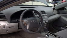
Step 1 – Disconnect battery and secure steering wheel
Disconnect the negative (black) battery cable. Move the terminal to an area where it cannot come into accidental contact with the battery post. Another option is to wrap the terminal with electrical tape. The goal here is make sure that no contact occurs.
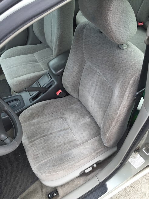
Inside the steering wheel is a clock spring. The wiring to the clock spring can only be rotated about three times in one direction without breaking. Because it's easy to accidentally rotate the wheel while the rack is being disconnected, tying the seat belt to the wheel ensures no rotation will occur. Steering wheel locking tools are also made for this purpose.
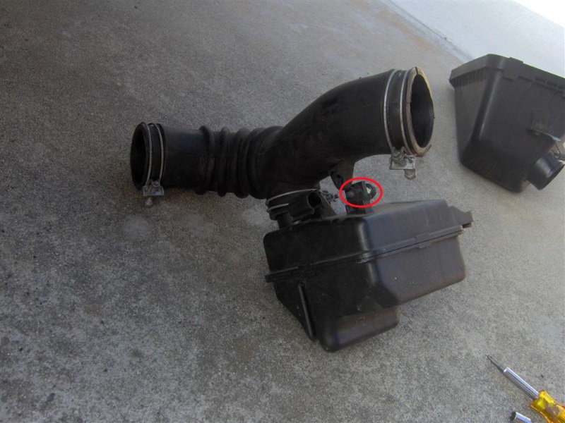
Step 2 – Remove air cleaner and piping from throttle body
Remove the intake air temperature sensor by squeezing the connector plug's flexible tab and pulling away from the intake. Disconnect the mass air flow sensor connector (if equipped). Loosen all the clamps holding the intake piping to the air box and throttle body with a Phillips head screwdriver. Additional hoses connected to the intake pipe may instead be disconnected by squeezing the clamps. Channel lock pliers work well for this type of clamp.
Now remove the bolt on the driver's side of the air box. On the sides of the air box are latches. Pull/release the latches to separate the top from the bottom. Once the top portion and air filter are removed, you will have access to the three bolts holding the bottom portion of the air box in place.
You may have to twist and pull with some force to remove the intake pipe from the throttle body.
Step 3 – Disconnect intermediate shaft from steering rack and steering column
The intermediate shaft has splined ends connected to universal joints. One end is accessed from the engine bay on the back side of the engine (on the driver's side). The other from inside the vehicle. Mark the position of the shafts in relation to the splines on the shaft with a white sharpie or similar tool. Use a 12mm socket to remove the bolts (one on each end) that connect the shaft to both the steering rack and steering column. You can loosen and remove the rubber boot at the interior side of the firewall for more access.
The center of the intermediate shaft collapses. Pull and wiggle the shaft from the universal joints.
Pro Tip
WD-40 or penetrating oil can help with bolt removal and separating the intermediate shaft from the universal joints.
Step 4 – Raise vehicle and remove wheels
If you do not have an electric or air powered impact wrench, remove the wheel cover by pulling it off the lug nuts. Pry/pull the edges of the cover away from the wheel and the cover will begin to snap free from the lug nuts. Loosen the lug nuts one full turn. Then, place wheel chocks behind the rear wheels and engage the parking brake. Raise the front of the vehicle with a floor jack and place a jack stand on each frame rail. Blocks of wood can be used on top of the jack stands to reduce the chance of damage to the underbody. After the car is securely raised, proceed to remove the wheels.

Figure 4. Areas along the pinch welds suitable for jack stands. 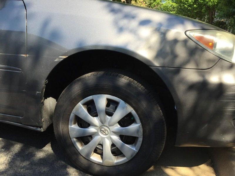
Figure 5. A Toyota Camry wheel cover.
(Related Article: How to Jack Up Your Car - CamryForums.com)
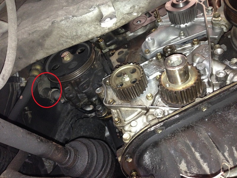
Step 5 – Disconnect power steering return line
Place a drain pan underneath the vehicle to catch the power steering fluid. Looking near the steering rack on the passenger's side of the car, you should see a return line attached to a steel line and the power steering reservoir.
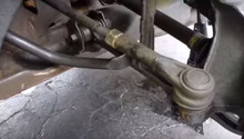
Step 6 – Disconnect outer tie rods from steering knuckles
Measure and record the thread length on the tie rod end below the toe adjustment nut. Straighten out the cotter pin and pull it away from the tie rod end. Using a 17mm socket, remove the nut from the tie rod end. You can use a pickle fork and a hammer or tie rod puller to dislodge the tie rod ends from the knuckles. If you plan on re-using the outer tie rods, opt for the tie rod puller because pickle forks are known to damage the rubber boots.

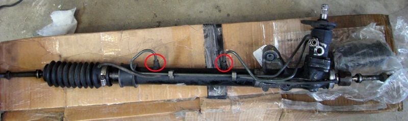
Step 7 – Disconnect power steering lines from steering rack
You will find these just below the input shaft on the gear head. One is larger than the other. Use a tubing wrench; otherwise, the edges of the lines may become rounded. Have a drain pan beneath the lines.
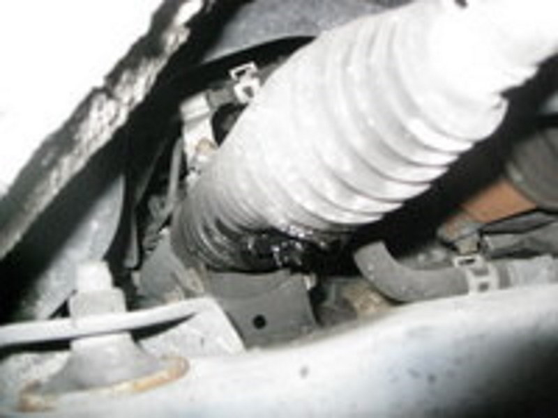
While you are near the rack, locate and remove the two hose clamps. One is bolted to the rack and the other is attached to two hoses near the rack.
Step 8 – Unbolt front sway bar from end links
The end links attach the sway bar to the lower control arms. One nut holds them together on each side. Pivot the sway bar out of the way. It doesn't have to be completely removed.

Step 9 – Remove steering rack from subframe
Two large bolts hold the rack to the subframe. You must remove the bolts (not the nuts) completely as the nuts have locking tabs.
A common issue with these bolts is finding they've become oval shaped. This can be fixed by welding circular steel washers onto the hole opening to re-create the correct shape.
Step 10 – Remove steering rack from vehicle
Removing/installing the rack will be much easier with two people. Once the rack is unbolted, lower it down and guide it out through the passenger's side wheel well. Transfer any undamaged components that are not included with the new rack. Record the length.
Step 11 – Begin installing new steering rack
Begin installation by centering the gear box. This requires an adjustable wrench and some tweaking to get it just right.
Once the new rack is slid into place, tighten the two bolts that secure it to the subframe at 100 ft. lbs. Reconnect the sway bar to the end links and tighten the nuts to 22 ft. lbs. Connect the power steering fluid lines to the rack and torque to 10 ft. lbs. (a little past snug). Reconnect the power steering return line and replace the hose clamp. Install the two hose clamps that were removed in Step 7.
Step 12 – Assemble and adjust tie rods
Assemble the tie rods ends (if necessary) and slide them into place on the steering knuckles. Secure the tie rod ends by tightening the nut, but do not torque it yet. Adjust the tie rods to have the same amount of exposed thread as the original.
Install the front wheels. Measure the distance between the front of each tire compared to the rear of each tire. A higher reading at the front will indicate a "toe-out" setting. The opposite will indicate a "toe-in." Adjust the tie rods to make the toe equal. You should have an alignment performed after doing this because this step is just to get your vehicle to the alignment shop.
Torque the tie rod end lock nuts to 36 ft. lbs.
Step 13 – Install intermediate shaft
Place the boot onto the shaft. Slide the shaft at its original position into the steering column. Tighten the universal bolt to 26 ft. lbs. Tighten down the firewall boot and double check that the steering wheel/tires are straight. Slide the other end of the shaft back into the steering rack and torque the bolt to the same value.
Step 14 – Fill and bleed the power steering fluid
Fill the system with power steering fluid to the maximum level. Install the air box and breather hose. Start the engine and slowly turn the wheel all the way to the right. Do not let the wheel rest against the bump stop (farthest point of travel in either direction). Top of the fluid as needed. Turn the engine off and leave the wheel at this position for several minutes. Do the same thing in the left direction.
Start the engine again and turn the wheel completely one direction to the other several times. Re-check the fluid. Check around the engine bay for leaks.
Lower the vehicle and torque the wheels to 110 ft. lbs. Begin your test drive, noting the placement of the steering wheel while the vehicle is traveling straight. If the wheel is not centered, remove one end of the intermediate shaft and adjust as needed. It's recommended you get a full alignment done for accurate toe settings.
Featured Video: Installing New Steering Rack
Related Discussions
- Rack and Pinion Replacement 2005 Camry - CamryForums.com
- Steering Rack Removal - CamryForums.com