Backup Camera Install
#1
 09-25-2015, 09:03 PM


2009 Camry SE 2.4L
Decided to install the backup camera today. In the following posts I will detail the install of the monitor.
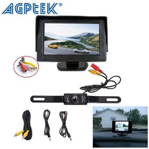
I bought this kit off Amazon for $39.99. I put the same on my Tacoma and so far it has been fine. The biggest complaint I have is the wires are a TINY gauge. Stripping them and wiring up a connector is a PITA. They should have used 16ga considering the distance the wire path may run. Looks more like 22 or smaller. AGPtek� Rear View Camera Adjustable Monitor Back up LED Night Vision CMOS Wide Angle Cam w/7 4.3" TFT LCD Screen & Back up License Plate
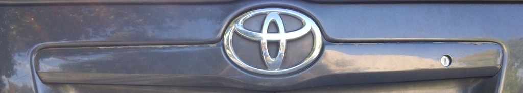
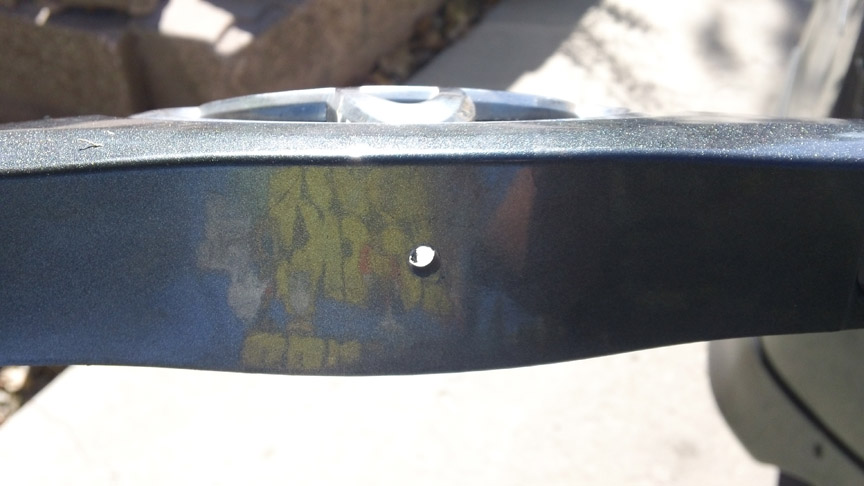
I wanted to get as clean an install as possible with minimal chance of water intrusion into the trunk, so I decided I will go through the logo covering piece above the plate, and drill into the trunk behind it.
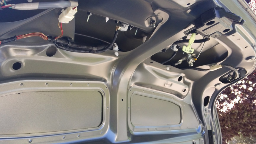
First I had to remove the liner in the trunk. I broke the first of 13 pins trying to figure out how to remove it. I am always doing that. After that the remaining 12 came out with no problem.

Now I had access to the wiring, and where I would run my cam wiring.
Decided to install the backup camera today. In the following posts I will detail the install of the monitor.
I bought this kit off Amazon for $39.99. I put the same on my Tacoma and so far it has been fine. The biggest complaint I have is the wires are a TINY gauge. Stripping them and wiring up a connector is a PITA. They should have used 16ga considering the distance the wire path may run. Looks more like 22 or smaller. AGPtek� Rear View Camera Adjustable Monitor Back up LED Night Vision CMOS Wide Angle Cam w/7 4.3" TFT LCD Screen & Back up License Plate
I wanted to get as clean an install as possible with minimal chance of water intrusion into the trunk, so I decided I will go through the logo covering piece above the plate, and drill into the trunk behind it.
First I had to remove the liner in the trunk. I broke the first of 13 pins trying to figure out how to remove it. I am always doing that. After that the remaining 12 came out with no problem.
Now I had access to the wiring, and where I would run my cam wiring.
Last edited by DIYDad; 09-25-2015 at 09:11 PM.
#2
09-25-2015, 09:04 PM
Now I had to remove the piece with the Toyota logo. 5 or 6 10mm nuts to remove that hold the plastic piece in place.
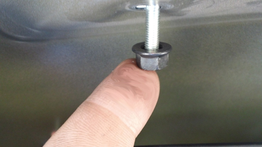
There is a plastic clip to depress as well.

And the logo is held in with a PITA large white plastic nub you have to press in to get it to allow it to remove. No pic of that, but you will see it if you do it.
Once it was off I made a pilot hole in it to ease the larger hole. In the end I had to run a 1/2 inch bit to make the hole wide enough to get the wire harness ends on the cam through it. Same with a hole I drilled into the trunk. That hole sits behind the plastic trim I removed, providing better water intrusion protection.
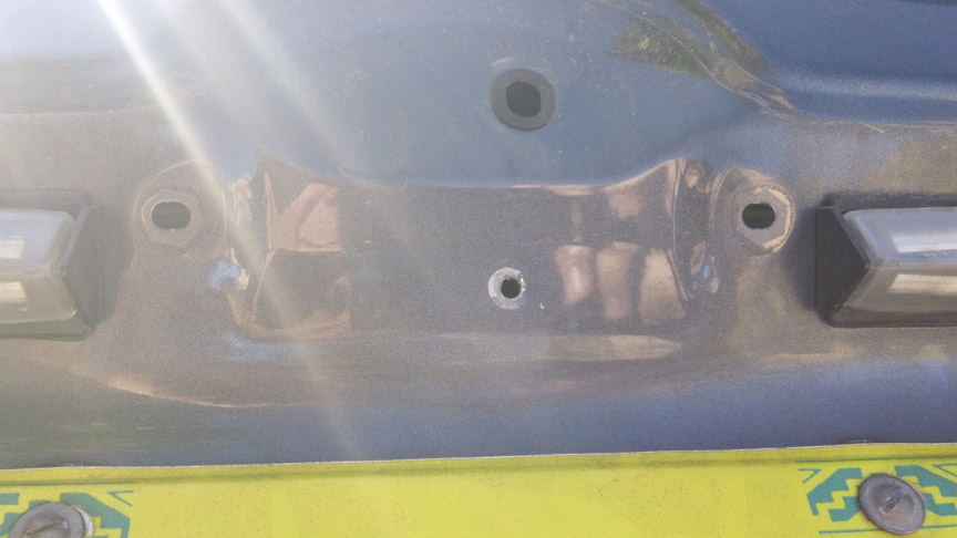
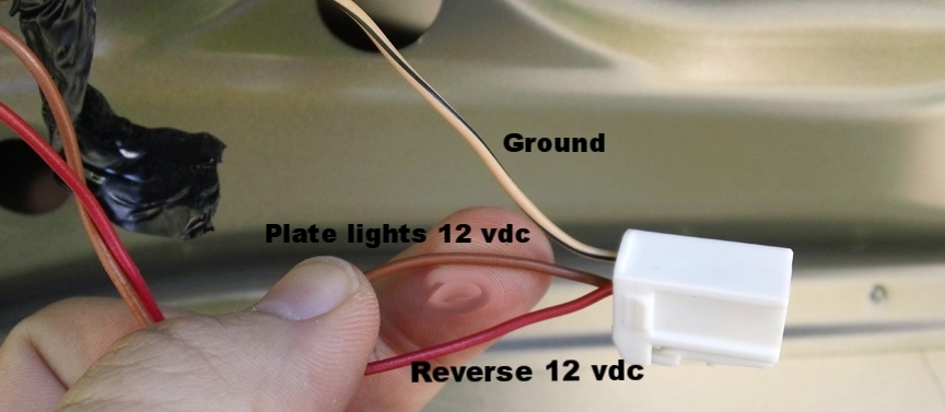
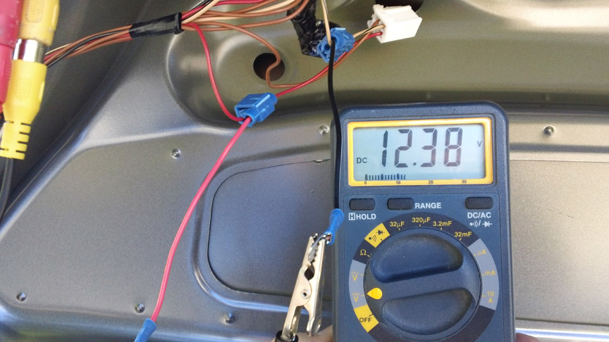
I opted to tie into the driver side rear light assembly. This assembly - which has the reverse backup light - is in the trunk lid. I disconnected the wire harness coming from the fuse panel - it has three wires. The red is the 12 vdc that gets energized when in Reverse. The brown gets 12 vdc (mine gave over 13 volts) when you put on the headlights. This wire powers the lights for the license plate. The white/black stripe is ground.
There is a plastic clip to depress as well.
And the logo is held in with a PITA large white plastic nub you have to press in to get it to allow it to remove. No pic of that, but you will see it if you do it.
Once it was off I made a pilot hole in it to ease the larger hole. In the end I had to run a 1/2 inch bit to make the hole wide enough to get the wire harness ends on the cam through it. Same with a hole I drilled into the trunk. That hole sits behind the plastic trim I removed, providing better water intrusion protection.
I opted to tie into the driver side rear light assembly. This assembly - which has the reverse backup light - is in the trunk lid. I disconnected the wire harness coming from the fuse panel - it has three wires. The red is the 12 vdc that gets energized when in Reverse. The brown gets 12 vdc (mine gave over 13 volts) when you put on the headlights. This wire powers the lights for the license plate. The white/black stripe is ground.
#3
09-25-2015, 09:04 PM
Next I tapped into the Red and White wires, and ran pigtails off that had spade connectors. This will allow me to disconnect the camera in the future to change it out if I need to. I chose to use red 16ga wire for the Hot to the camera, and black 16ga wire for the camera ground.
I tested this connection by putting the car in reverse, and also testing when the vehicle was on but not in reverse. As you can see, got the volts I need!
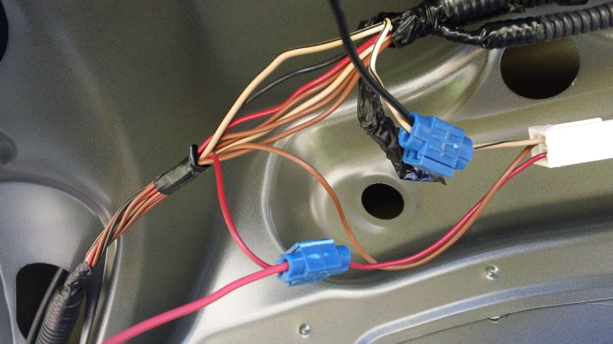
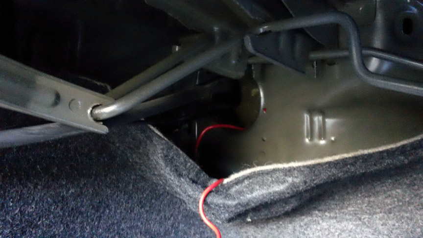
I taped up all my connectors and did a nice wire tuck and tape into the trunk inners to make it tidy. Then I put the liner back in and ran the camera video wire out the same exit that the light wire bundle and trunk release cable goes through. Nice and neat.
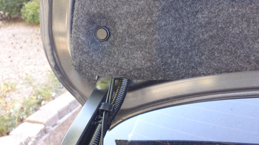
A close up of how the cam wire runs:
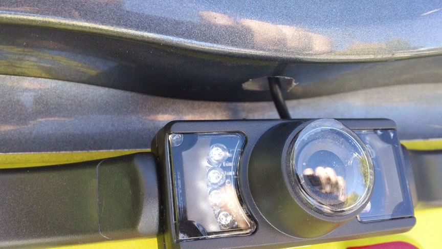
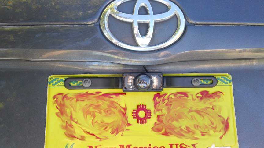
And the finished product:
Tomorrow I will tap into the rear light feed at the fuse panel and wire up the monitor. I'll run the video cable, plus a 16ga wire back to the cam for future switch operation, under the door jam sill (where all the wires run now). I'll take pics of all that and post when it is done. I tested the cam by tying it in temporarily and it worked perfect!
I tested this connection by putting the car in reverse, and also testing when the vehicle was on but not in reverse. As you can see, got the volts I need!
I taped up all my connectors and did a nice wire tuck and tape into the trunk inners to make it tidy. Then I put the liner back in and ran the camera video wire out the same exit that the light wire bundle and trunk release cable goes through. Nice and neat.
A close up of how the cam wire runs:
And the finished product:
Tomorrow I will tap into the rear light feed at the fuse panel and wire up the monitor. I'll run the video cable, plus a 16ga wire back to the cam for future switch operation, under the door jam sill (where all the wires run now). I'll take pics of all that and post when it is done. I tested the cam by tying it in temporarily and it worked perfect!

#5
09-25-2015, 11:11 PM
Thanks. My plan is to run a 12 vdc dedicated wire back, that is tied into the ACC connection. I will put a switch on it, and tie that powered wire back into the camera wire and the monitor wire. That way I can flip the switch and turn on the rear view when driving, to see how close some d bag may be tailing me or whatever.
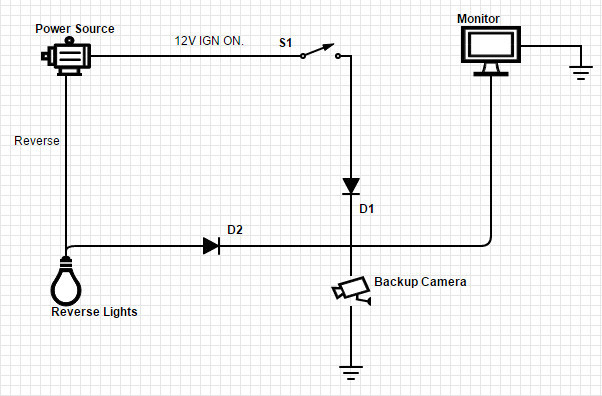
In order to keep the backup lights from flaring on when I do that (it would feed power back down the tap into the light) I will put diodes on the circuit to keep power from flowing back into the tail lights. Have two standing by. Will solder up the diode connections tomorrow, then install them at some point. Sort of like this, but the monitor is going to be wired a tad differently based on how I connected it all today.
In order to keep the backup lights from flaring on when I do that (it would feed power back down the tap into the light) I will put diodes on the circuit to keep power from flowing back into the tail lights. Have two standing by. Will solder up the diode connections tomorrow, then install them at some point. Sort of like this, but the monitor is going to be wired a tad differently based on how I connected it all today.
#6
09-26-2015, 10:53 PM
Today I tackled running the wire from the trunk to the center console, and wired up the monitor. I decided to go ahead and wire in my diodes and switch as well. The idea was, I wanted to be able to power on the camera when driving forward. The trick was, since I tapped the camera into the reverse light wire, to not send power back into the reverse lights causing them to come on. That is where the diodes come in.
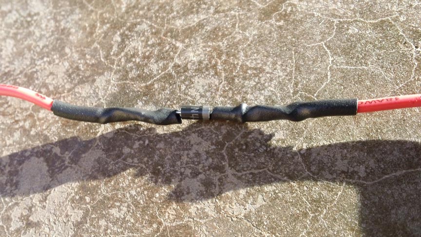
I made a little diode insert, running 16ga wire off each end, soldering the wire to the diode. To clean it up I then put heat shrink tubing over it and, using my heat gun, shrunk it down. This covered the ends that could conduct, but left the marking open so I could see it later. I tested each on my multimeter. For those interested but not aware, silicon diodes (used and pictured) allow current to flow in only one direction. In the image that is noted by the grey band. Power flows from left to right in the image, but cannot flow from right to left. This was critical as I needed to flow power from the backup light circuit, but NOT flow power back into the backup light circuit. To test I had a good connection I set my meter to diode test mode and put the red lead on the left, black lead on the right. That gave me .5xx volts. Swapping gave me OL, meaning no flow. That meant it was good to go. I made two of these. One was to tie into where I tap into the backup light, the other for where I tied the monitor power together.
The reason I needed to put another diode at the monitor was due to the fact that I ran a dedicated wire all the way back from the monitor to the camera, so that I could give myself a dedicated 12 vdc pathway independent of the backup light circuit. That meant I had to tie together three wires at the monitor: the wire running back to the camera (which tied in with the backup light and camera wires), the power lead from the monitor, and a wire I tapped into the power socket in my console. Since the wire running back to the camera/backup light was going to be twisted together with the ACC 12 vdc wire, I had to isolate that pathway with a diode also.
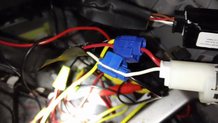
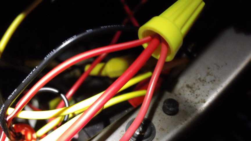
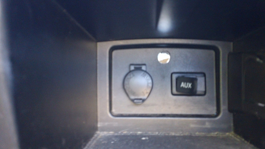
Here you see the taps into the power port that goes into the back of the console where the AUX and POWER ports are. Red is 12 vdc tied to ACC/ON at the ignition cylinder, and the white/black is again ground. Since the monitor had a dedicated wire running back to the camera, I could twist those leads together at the back end, meaning I only needed one additional wire to give me my ACC/ON 12 vdc to power it all up via a switch. That is the yellow wire tapped into the red.
The monitor power lead, wire running back to the camera, and diode lead are all twisted together, giving me power when in reverse and keeping power from running back into the camera when I close the circuit with my ACC 12 vdc connection at the switch.
I made a little diode insert, running 16ga wire off each end, soldering the wire to the diode. To clean it up I then put heat shrink tubing over it and, using my heat gun, shrunk it down. This covered the ends that could conduct, but left the marking open so I could see it later. I tested each on my multimeter. For those interested but not aware, silicon diodes (used and pictured) allow current to flow in only one direction. In the image that is noted by the grey band. Power flows from left to right in the image, but cannot flow from right to left. This was critical as I needed to flow power from the backup light circuit, but NOT flow power back into the backup light circuit. To test I had a good connection I set my meter to diode test mode and put the red lead on the left, black lead on the right. That gave me .5xx volts. Swapping gave me OL, meaning no flow. That meant it was good to go. I made two of these. One was to tie into where I tap into the backup light, the other for where I tied the monitor power together.
The reason I needed to put another diode at the monitor was due to the fact that I ran a dedicated wire all the way back from the monitor to the camera, so that I could give myself a dedicated 12 vdc pathway independent of the backup light circuit. That meant I had to tie together three wires at the monitor: the wire running back to the camera (which tied in with the backup light and camera wires), the power lead from the monitor, and a wire I tapped into the power socket in my console. Since the wire running back to the camera/backup light was going to be twisted together with the ACC 12 vdc wire, I had to isolate that pathway with a diode also.
Here you see the taps into the power port that goes into the back of the console where the AUX and POWER ports are. Red is 12 vdc tied to ACC/ON at the ignition cylinder, and the white/black is again ground. Since the monitor had a dedicated wire running back to the camera, I could twist those leads together at the back end, meaning I only needed one additional wire to give me my ACC/ON 12 vdc to power it all up via a switch. That is the yellow wire tapped into the red.
The monitor power lead, wire running back to the camera, and diode lead are all twisted together, giving me power when in reverse and keeping power from running back into the camera when I close the circuit with my ACC 12 vdc connection at the switch.
#7
09-26-2015, 10:54 PM
I ran the video cable and dedicated 16ga wire through the hole already in the rear plate going back behind the rear seat.
I was able to squeeze my hand in by pushing in the seat, so I did not need to remove the seat back. YES! That is one PITA job to do, so I was VERY glad I did not have to remove it.
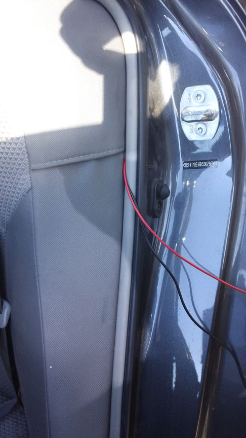
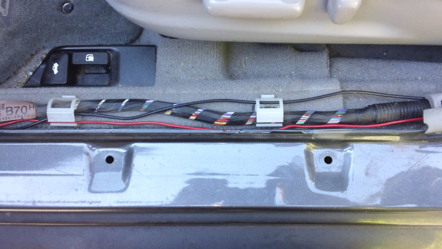
I kept feeding the wires under the trim, then removed the sills at the bottom and ran the wires along it. Keeps it safe and out of the way. The black wire is the video line, the red is the dedicated wire running from the monitor to the camera.
I removed all the trim from the console to get access to where I needed to do my work.
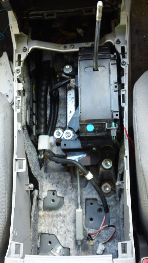
Pulling the center piece out (had to disconnect the AUX and power port), I drilled a 1/2 inch hole to run the monitor wires through. This kit allows for two video connections, so there are two video connectors and a power/ground connector I needed to pass through the hole.
I bought a blue LED rocker switch and ran ground, 12 vdc from the power port, and the diode lead back to the rear. It was too dark to take a good pic of that so I will do it tomorrow and post. For now I tucked it out the side of the trim, and will find a permanent place for it later. Put it all back together, and it works great!
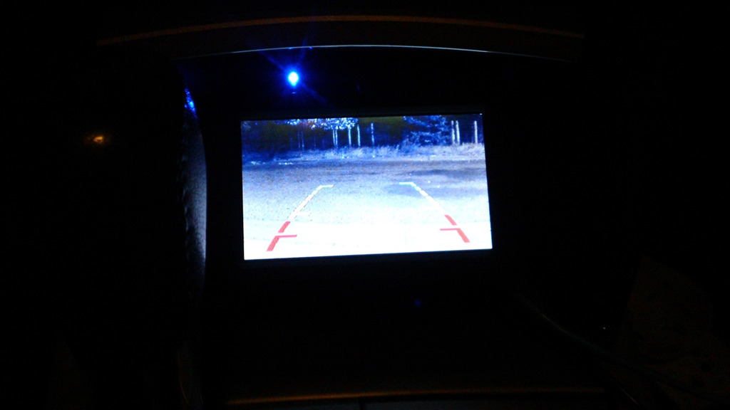
Here is a shot at night, with the night vision capability of the camera. I have this on with the switch, not in reverse gear. That blue light at the top of the monitor is a USB connector plugged into that aux port that feed my iPod - has nothing to do with the camera system.
Tomorrow I will post pics of the rear wire splices and the switch and system in daylight.
I was able to squeeze my hand in by pushing in the seat, so I did not need to remove the seat back. YES! That is one PITA job to do, so I was VERY glad I did not have to remove it.
I kept feeding the wires under the trim, then removed the sills at the bottom and ran the wires along it. Keeps it safe and out of the way. The black wire is the video line, the red is the dedicated wire running from the monitor to the camera.
I removed all the trim from the console to get access to where I needed to do my work.
Pulling the center piece out (had to disconnect the AUX and power port), I drilled a 1/2 inch hole to run the monitor wires through. This kit allows for two video connections, so there are two video connectors and a power/ground connector I needed to pass through the hole.
I bought a blue LED rocker switch and ran ground, 12 vdc from the power port, and the diode lead back to the rear. It was too dark to take a good pic of that so I will do it tomorrow and post. For now I tucked it out the side of the trim, and will find a permanent place for it later. Put it all back together, and it works great!
Here is a shot at night, with the night vision capability of the camera. I have this on with the switch, not in reverse gear. That blue light at the top of the monitor is a USB connector plugged into that aux port that feed my iPod - has nothing to do with the camera system.
Tomorrow I will post pics of the rear wire splices and the switch and system in daylight.
#8
09-27-2015, 03:43 PM
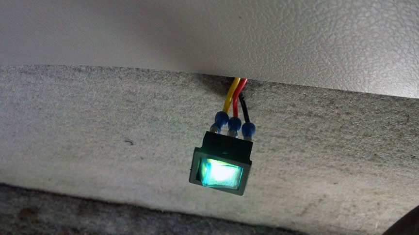
The LED switch. For now it is just peeking out of the trim where the console is (shift and cup holder). Before too long I'll find a permanent home for it. Yellow wire is ACC 12 vdc, red is load (camera/monitor), black is ground.
Hard to get a good shot of the monitor as the sun was not cooperating. I have the switch on, car in D (stopped in the street). Yeah, that's a shin guard jammed into the console to keep the monitor from sliding back (lol). Don't want to sticky tape it there yet. Like the switch I'll place it "permanently" later on.
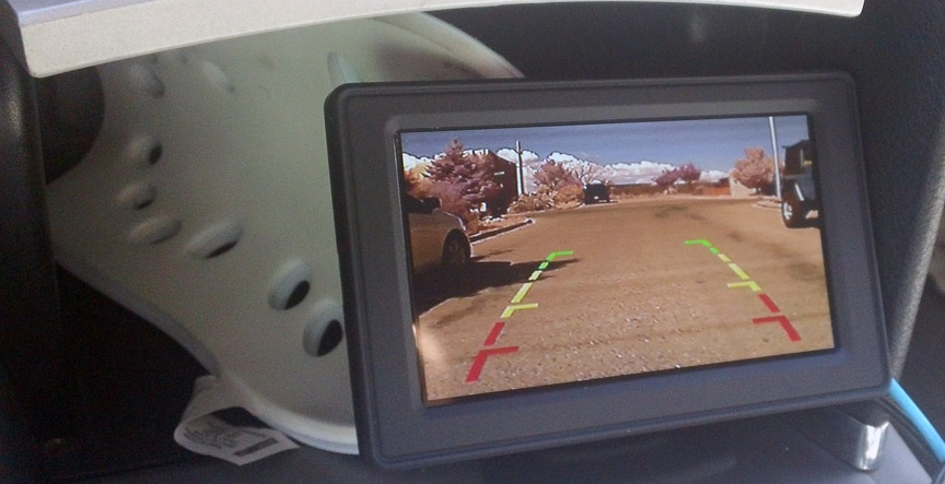
I have "noise" lines on the monitor that was not there when I tested a simple hook up in the trunk, and is not present in my other unit on my Tacoma. I figure it is one of three things:
1). The video cable was not long enough, so I had to join it right about the steering column. I do not have a video connector (F to F barrel), so I am using an audio connector right now. Not sure if the quality is different due to that.
2). I have the camera grounded into the backup light plug, and the monitor grounded into the Power port plug, so may be getting some noise due to that. In the Tacoma each is simply grounded to the chassis (different points).
3). The diodes are causing an issue.
Each of these I can isolate some day, not a big deal as it is not causing any great issue. For now the camera is working and I will move on to installing the backup sensors next. At some point I will isolate a "clean" ACC line and battery 12 vdc at the fuse box and wire up my 8 port mini fuse box for these types of projects, instead of tapping into the power ports.
Hard to get a good shot of the monitor as the sun was not cooperating. I have the switch on, car in D (stopped in the street). Yeah, that's a shin guard jammed into the console to keep the monitor from sliding back (lol). Don't want to sticky tape it there yet. Like the switch I'll place it "permanently" later on.
I have "noise" lines on the monitor that was not there when I tested a simple hook up in the trunk, and is not present in my other unit on my Tacoma. I figure it is one of three things:
1). The video cable was not long enough, so I had to join it right about the steering column. I do not have a video connector (F to F barrel), so I am using an audio connector right now. Not sure if the quality is different due to that.
2). I have the camera grounded into the backup light plug, and the monitor grounded into the Power port plug, so may be getting some noise due to that. In the Tacoma each is simply grounded to the chassis (different points).
3). The diodes are causing an issue.
Each of these I can isolate some day, not a big deal as it is not causing any great issue. For now the camera is working and I will move on to installing the backup sensors next. At some point I will isolate a "clean" ACC line and battery 12 vdc at the fuse box and wire up my 8 port mini fuse box for these types of projects, instead of tapping into the power ports.
#9
09-28-2015, 01:32 AM


Thread
Thread Starter
Forum
Replies
Last Post