Toyota Camry 2002-2006: Fuel Diagnostic Guide
The fuel system is tasked with supplying fuel from the gas tank to the combustion chamber. Fuel pressure's volume must be correct for smooth engine operation. When one of these components is out of sync, a misfire, stumble, and/or a trouble code may become present.
This article applies to the Toyota Camry (2002-2006).
Inside the fuel tank is the fuel pump and fuel pressure regulator. When the ignition is turned to the "on" position, the pump energizes and supplies fuel pressure to the injectors. Once the engine reaches a certain point in its rotation, the computer commands the injector to open. Pressure is maintained at all times while the engine is running to ensure quick and effective engine response.
Emissions standards require that fumes from the gasoline in your tank be routed into your engine to be burned. This is the E.V.A.P. system's job. Once engine running conditions are met (highway cruising), the purge valve opens and engine vacuum draws in the fumes inside the charcoal canister.

Materials Needed
- Socket set (8mm-14mm)
- Ratchet
- Digital volt Ohm meter
- Fused jumper wires
- Scan tool
- Injector noid light
- Flashlight
Begin your diagnosis by scanning your Camry for trouble codes. This can be done at most auto parts stores at no cost.
Filling your tank with fresh gasoline from a station you've frequently visited will help rule out the possibility of bad gasoline. Do not overfill your gas tank! Topping off the tank (continuing to pump after the pump handle releases) may generate a trouble code.
It is essential to have a smoke machine and scan tool capable of bi-directional control when diagnosing the E.V.A.P. system. The smoke machine makes it easy to locate vacuum leaks and the bi-directional control allows the user to control the vent/purge valves operation during the test.
Step 1 – Perform a visual inspection
Start at the gas cap. Make sure the cap is fully tightened. There should be instructions on the gas cap, fuel door, and/or owner's manual. Often times, these instructions will state "turn the gas cap until a click is heard." A loose gas cap will create a fault in the E.V.A.P. system. This system uses a vacuum to transfer gases in the gas tank into the engine. A leaking gas cap will not allow this vacuum to generate.
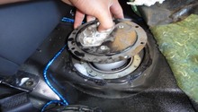
With the gas cap open, have another person turn the key to the "key on engine off" (ignition on) position. This will be one position before start. Listen for the hum of the fuel pump. This noise should be noticeable for several seconds as the pump primes. No noise indicates a faulty fuel pump or wiring problem in the fuel pump circuit.
Move to the engine bay. Visually inspect the fuel lines leading to the fuel rail, the rail itself, and the fuel injectors. These should be leak-free and in good condition. With the engine running, you should be able to feel and hear a click coming from each injector. This click is the sound of the pintle valve opening and closing. No click indicates a faulty injector or injector wiring problem.

If noise is present at the fuel pump, then continue with Step 3.
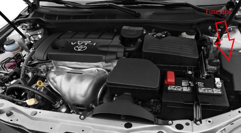
Step 2 – Check the fuel pump fuse/relay
In the engine bay you will see a fuse/relay box to the right of the battery. Remove the box lid and read the diagram on the bottom side. Locate the E.F.I. fuse. Visually inspect the fuse for an unbroken connection. If the fuse appears dark/black inside, it's blown and needs to be replaced. Check the fuse continuity with a digital volt Ohm meter.
Now locate the E.F.I. relay. This is a four prong relay. Remove the relay with an upward pull and inspect the relay box sockets for corrosion. Test the relay by applying power (a 9-volt battery works well) to one of the two prong pairs. One of these prong pairs should generate the magnetism needed to close the relay switch. This action can be heard and felt as a click. Once this noise is heard, test the other prong pair for continuity.
There is another relay in the fuel pump circuit; although, it's harder to reach. This relay is known as the circuit opening relay. It's located on top of the E.C.U. between the driver and passenger foot well behind the radio. Access to the relay can be gained by pulling pack the front inner corner of passenger side carpet. Test this relay in the same manner as the E.F.I. relay.
Step 3 – Test the fuel injectors
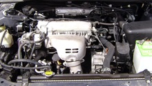
Locate the fuel injectors. On the four cylinder, they are beneath the plastic engine cover. The injectors are harder to access on the six cylinder. They are next to and beneath the intake manifold. Remove the electrical connectors one at a time and install an injector noid light. This light flashes every time the engine computer commands the injector to energize. Once the noid light is connected, start the engine and record the results. No flash indicates a problem with the fuel injector wiring circuit.
If a noid light is not available, the injectors resistance can be check with a digital volt ohm meter. Record each injectors reading at the prongs on the injector electrical connection. Each injectors reading should be similar at 11.6 to 12.4 Ohms. If one injectors reading is drastically different, it should be replaced.

Step 4 – Test the fuel pump
If your relays and fuse checked out okay in Step 2, it's time to check for power and ground at the fuel pump. For a complete wiring diagram, you'll need to locate service information such as AllDatadly.com or a local Toyota dealer. Remove the rear seat and locate the fuel pump electrical connector. Unplug the connector and check for 12 volts with a digital volt meter connected to the battery positive wire and a good ground. The ground can be the white/black wire on the connector or a good body ground; although, your test will be inconclusive if the connector ground wire is faulty. Once your meter is correctly set up, turn the ignition on. The lack of 12 volts present on the power wire indicates a wiring problem between the pump connector and the opening circuit relay.
A voltage drop test is another way to test the fuel pump and its wiring. You'll need two fused jumper wires (10 amp). Connect one end of the jumper wires to battery positive and negative. Connect the positive end to the power terminal on the fuel pump and the negative end to the ground terminal. Once the connection is made, the fuel pump should energize. If the pump energizes, you know conclusively there is a problem in the fuel pump wiring circuit. Test the power wiring by keeping the positive jumper wire connected to the fuel pump power terminal, but remove the negative jumper wire. If the pump now operates, you've isolated the power wire as the fault. Test the ground wire using the same procedure. With the fuel pump energized, measure the ground wires voltage by attaching one of your meter leads to the ground terminal of the fuel pump connector and the other to the negative battery. This wire should have less than 100 milli-volts; otherwise, high resistance is present.

Related Discussions
- P0440 Code, Please Help! CamryForums.com
- Fuel Issue, P0440 - CamryForums.com
- Four Cylinder Fuel Problems - CamryForums.com