Transmission Fubar
#11
 04-06-2015, 01:30 PM


The error codes I received were 0746, 0776 and 0796. I never received 1760. Tracing it all down, I am under the impression it is this part: 35290-45010.
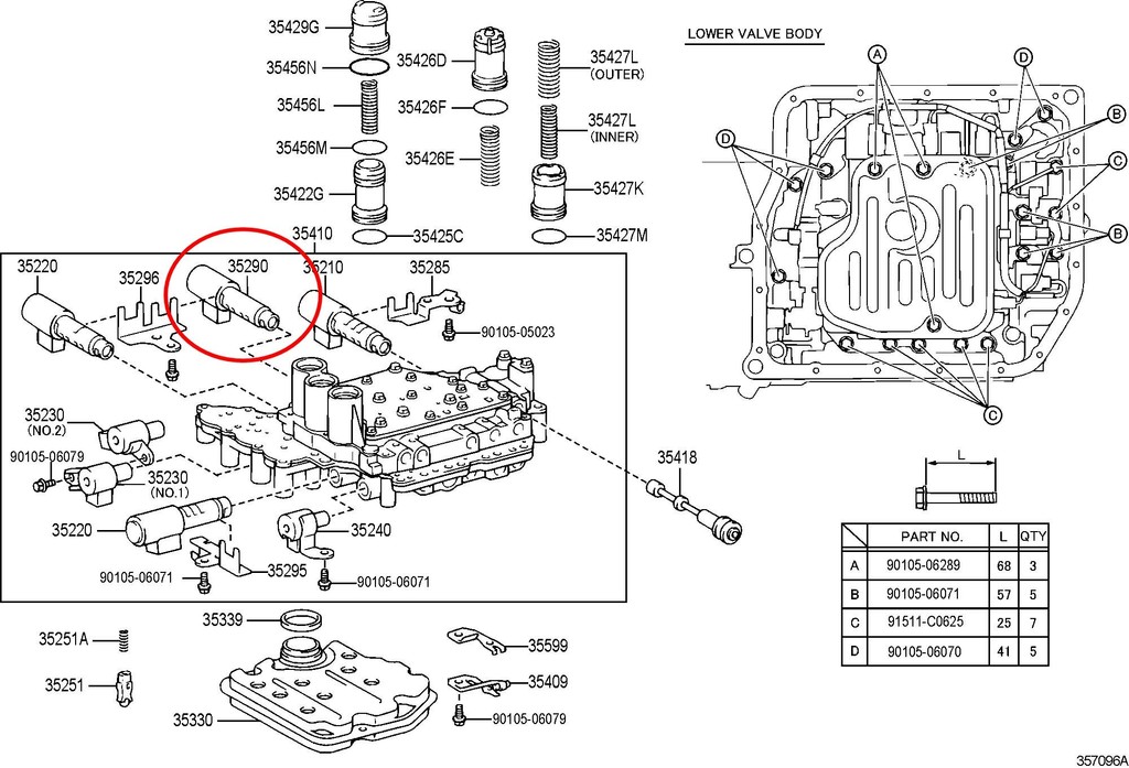
I would access it by removing the lower valve body, correct?
I would access it by removing the lower valve body, correct?

#15
04-09-2015, 11:32 AM
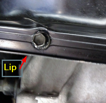
I have been thinking of the design of the pan for the transmission, and how it lends itself to a PITA to get to those 5 suck bolts that lie under the frame. The pan flares out at the edges for some reason that I can't quite grasp, creating a groove of sorts that the bolts line up in. On those 5 suck bolts, that means you cannot get a flush contact point on them with a wrench: you have to hit them at a slight angle due to that ridge. I don't have a ratchet/socket set that is shallow enough to work on those, so stuck using my ratcheting 10mm combo wrench.
Trying to figure out what would be the harm in grinding down that lip in that area so I could come at those bolts square on with my wrench. As long as I don't deform the shape of the pan by pressing down hard while grinding, why not? That lip has no effect on the seal, may be just there to protect the bolts from ground debris or something?
Trying to figure out what would be the harm in grinding down that lip in that area so I could come at those bolts square on with my wrench. As long as I don't deform the shape of the pan by pressing down hard while grinding, why not? That lip has no effect on the seal, may be just there to protect the bolts from ground debris or something?
#17
04-11-2015, 03:46 PM
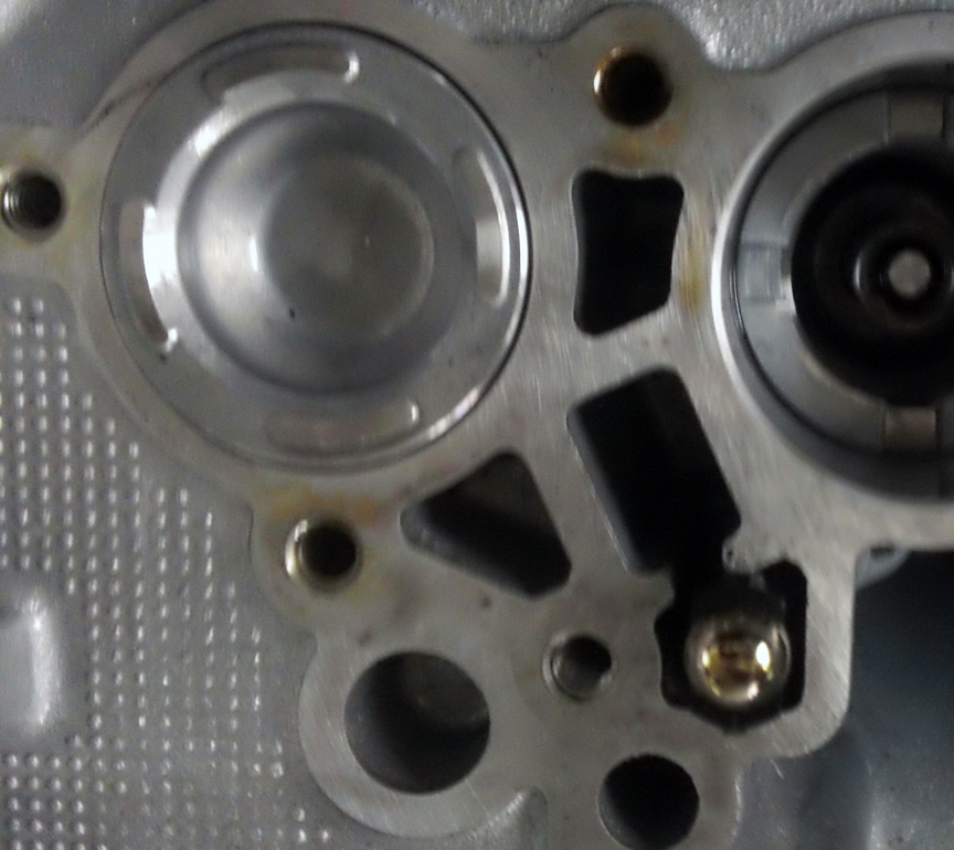
This is one of the worst illustrations in the FSM. The damn check ball body toppled out when lowering the valve body, so it is not clear to me exactly where it goes. Anyone know if it is the red circled area I have in this image? If so it looks like the ball side is up in this image, correct? Or does that thing go inside the spring?
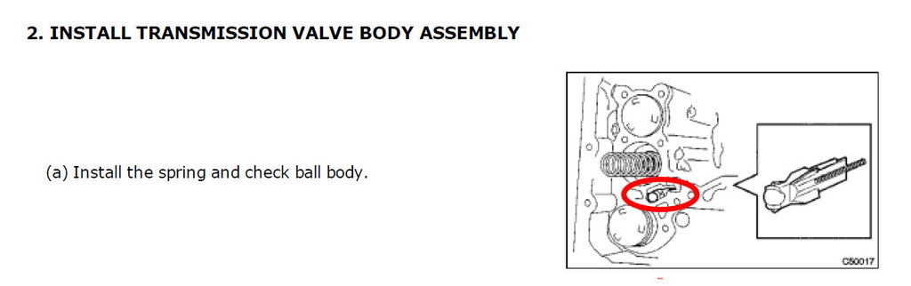
Here is the real image inside the tranny, that the illustration is referring to.
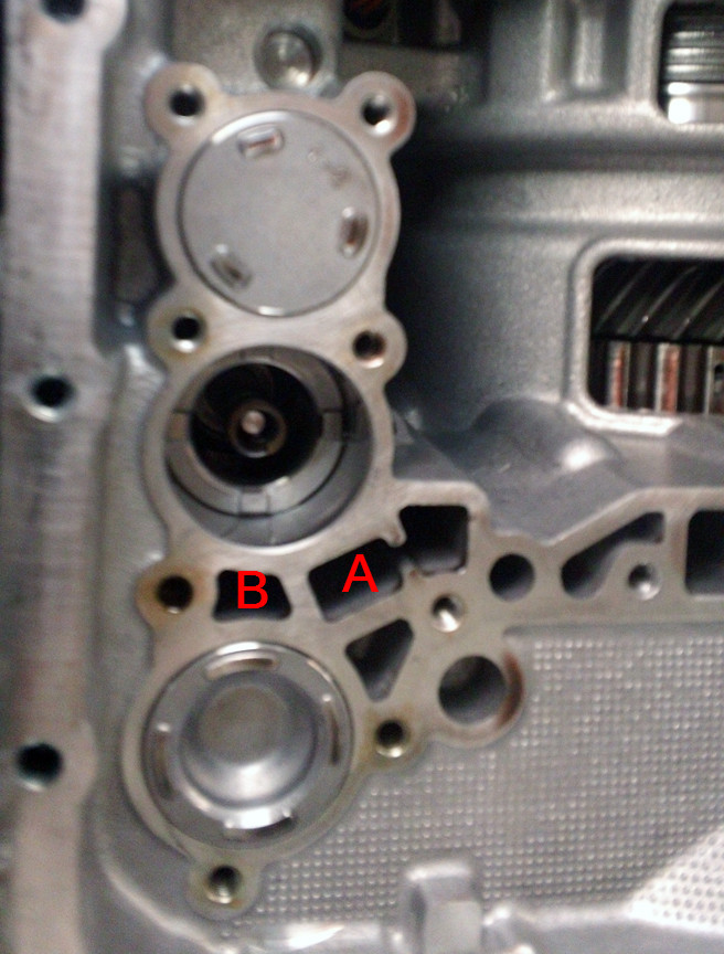
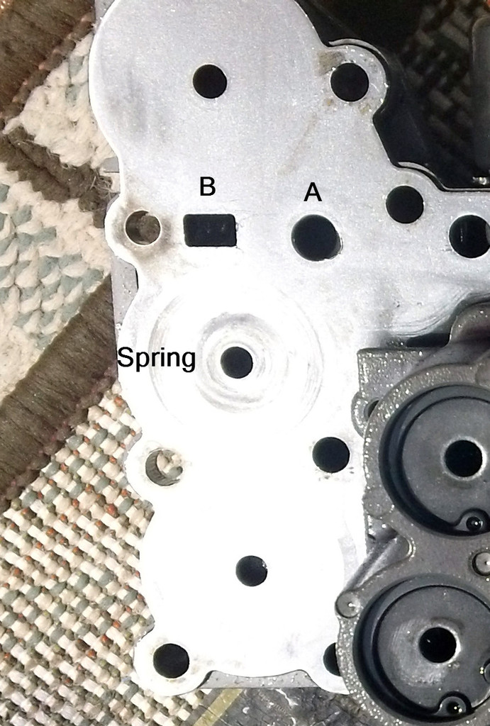
On the inside (tranny side) of the valve body, I think that brass ball rests in what I have labeled A, right? Not B? And WTF man, talk about Mission Impossible. How do they expect you to get that spring and check ball body in? Nothing to lock into inside the tranny, and nothing on the valve body to hold it upright. Seems like I am going to need a small miracle to get this in, even with lifting the valve body with a jack.
UPDATE:
Maybe this?
Here is the real image inside the tranny, that the illustration is referring to.
On the inside (tranny side) of the valve body, I think that brass ball rests in what I have labeled A, right? Not B? And WTF man, talk about Mission Impossible. How do they expect you to get that spring and check ball body in? Nothing to lock into inside the tranny, and nothing on the valve body to hold it upright. Seems like I am going to need a small miracle to get this in, even with lifting the valve body with a jack.
UPDATE:
Maybe this?
Last edited by DIYDad; 04-11-2015 at 04:54 PM.
#19
04-11-2015, 04:51 PM
The only place that makes sense is in the hole A. It doesn't fit in B, and in the photo above where I try to get it into that hole to the right of A it does not seat flush, so the valve body will not install. It flushes in perfect inside hole A, but there is nothing to hold it in place. I am stumped.
Last edited by DIYDad; 04-11-2015 at 04:55 PM.
#20
04-11-2015, 09:08 PM
I improvised. Since neither spring nor check ball had any possibility of staying put, I ran a piece of electrician tape to hold them in place, then raised the valve body and when up close I pulled the tape. I supported the valve body with a jack then, leaving a gap, inspected the spring and check ball with my boroscope. They seem to be fine.
And then the F-ing jack tore the temperature sensor off the transmission wire when I was letting it back down. The sensor got tangled up in the mechanics and off it came. So, I can solder it back in, no huge deal, but I need to know if there is a polarity to the two wires. Both are orange, neither seems to have a stripe I can see. Being a temp sensor I am not sure if it matters which wire goes to which pole. ?? And I have to figure out why one wire is much longer (now) than the other. Maybe the jack cut one of the wires, although I can't find a piece laying around. I am afraid it pulled it from the main harness, which would suck.
And then the F-ing jack tore the temperature sensor off the transmission wire when I was letting it back down. The sensor got tangled up in the mechanics and off it came. So, I can solder it back in, no huge deal, but I need to know if there is a polarity to the two wires. Both are orange, neither seems to have a stripe I can see. Being a temp sensor I am not sure if it matters which wire goes to which pole. ?? And I have to figure out why one wire is much longer (now) than the other. Maybe the jack cut one of the wires, although I can't find a piece laying around. I am afraid it pulled it from the main harness, which would suck.